Micro Hole Metal Stamping Processing Technical Problems
Apr 16, 2022
The definition of micro holes at home and abroad is: holes with a diameter of 0.1-1.0 ram are called small holes, and holes with a diameter of less than 01.mm are called micro holes. Therefore, the requirements for small hole punching are getting higher and higher.
At present, the definition of micro holes at home and abroad is: holes with a diameter of 0.1-1.0 ram are called small holes, and holes with a diameter of less than 01.mm are called micro holes. With the rapid development of the industry, the use of components with micro-holes as the key structure is increasing, the aperture size is getting smaller and smaller, and the precision requirements are getting higher and higher. Such as aero-engine turbine blade cooling holes, gem bearing holes, electron microscope gratings, PCB microplates, polymer composite material holes, diamond wire drawing dies, precision chemical fiber spinnerets, RP technology rapid prototyping equipment nozzle holes, optical fiber connectors, fuel Fuel injectors, ink jet holes of printers, red blood cell filters, and microstructures of high-end products such as micro-injectors and micro-pumps, etc. The workpiece materials of these products are mostly metal alloy materials, the micro-holes have a large aspect ratio, and the feature size is between 50 and 100 μm.
For the processing of micro-holes, due to the development of workpiece materials in the direction of high strength and high hardness, many parts need to use difficult-to-machine materials such as heat-resistant steel, stainless steel, die steel, cemented carbide, ceramics, diamond and other polymer composite materials. , In addition, the shape of the tiny holes is no longer a single circle, but tends to various complex shapes that can achieve specific functions, such as the three-lobed circular arc in the spinneret, the three-lobed edge, and the v-shaped. , hexagonal and other special-shaped holes, all of which put forward higher and updated requirements for the processing technology of micro holes. Specifically, the miniaturization industry requires that the processing technology should meet the characteristics of large batch, high efficiency, high precision, high density, short cycle, low cost, no pollution, net shape and so on, while in the traditional macro manufacturing field, the plastic forming process ( Blanking, bending, drawing, deep drawing, superplastic extrusion, undulation, embossing, etc.) precisely have these industrial advantages. Micro-stamping is a key process method in micro-plastic forming technology. This paper studies the micro-stamping process from the aspect of processing equipment development for the processing of micro-holes.
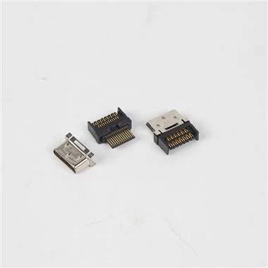
Micro hole metal stamping
In the manufacturing industry, the diameter of the micro-hole processing drill is generally above φ=0.27, and the tool material is tungsten steel or white steel imported from Japan. In the past, due to the high cost of etching processing and poor laser precision, with the improvement of the metal small hole punching process, It has been basically eliminated. Stable realization of mass production. With the increase in the functions of mobile phones, the distribution of printed circuit boards is increasingly dense, and the diameter of the micro-holes of the copper foil on the circuit board is also smaller, and the processing difficulty is further increased. The development trend of the filter screen used in the fuel nozzle of the internal combustion engine is generally the same, so the requirements for the punching of the small holes are getting higher and higher.
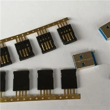
Micro hole metal stamping
There are many reasons why the punching needle is easy to break. It may be the reason of the punching needle itself, or it may be the design defect of the mold. It may also be a series of problems such as blanking materials. In fact, no matter what the problem is, we should try to solve the problem. Both the material plate and the die must be inlaid with guide posts and guide sleeves, wire cutting with slow wire or oil cutting, 0.02~0.06mm on both sides of the male splint, and 0.01mm on both sides of the stripping plate. The domestic practice is somewhat different. Generally, the unilateral tolerance of the male splint is ±5μ, and the unilateral side of the stripping plate is 0.01mm; when using slow wire, it can be considered to increase appropriately. If the punching needle is offset, in order to make the punching needle as short as possible, the gap should be properly placed, the guide post should be larger, and the gap with the guide sleeve of the die should not exceed 0.005mm on one side. The gap between the stripping plate is smaller than that of the lower template, generally 0.005mm on both sides and 0.02mm on both sides of the male splint. It doesn’t matter if the loose point is loosened.